


– Honda Motorcycle News – Concept / Prototype / Patent Announcements & Updates –
Have you ever thought about how cool it would be if your seat was adjustable electronically and automatically? What about those that are vertically challenged and don’t want to be on their tip-toes when coming to a stop at a red-light etc? How cool would it be if your motorcycle sensed you were coming to a stop and then the seat automatically adjusted itself to a lower position to where you could put both of your feet comfortably on the ground? There’s a ton of other ways that Honda could play with this setup so it’ll be interesting to see how it all pans out and if it ever makes it onto a production bike.

What do you think about the idea? Would you like to see Honda bring it to their production motorcycles in the near future?
Want to check out other new Motorcycle Technology Patents on what we might see on bikes in the future? Check them out by Clicking Here.
Below, you’ll find the entire patent document filing if you like to read through the nitty-gritty details and see what all goes into bringing new technology to market like this.
PATENT BACKGROUND
The present disclosure relates to a vehicle with a seating assembly for occupants to be seated thereon.
Japanese Patent Laid-Open No. 2008-081083 proposed vehicles such as motorcycles or the like which include a tilting mechanism for changing the position of a front seat depending on the vehicle speed. Japanese Patent Laid-Open No. 2008-081083 is aimed at taking a seat position depending on the vehicle speed for planting better footing and reducing air resistance.
SUMMARY
Heretofore, there have been vehicles where the seat position is variable depending on, for example, the vehicle speed, but they have not been designed to give consideration to vehicle body behavior depending on the acceleration or the like of the vehicle.
The rider of a two-wheeled vehicle can ride the vehicle more comfortably with fun by taking an appropriate riding posture on the basis of a different vehicle body behavior even if the vehicle speed remains unchanged.
If a novice who is not accustomed to driving a two-wheeled vehicle is prompted to take an appropriate riding posture on the vehicle, then their driving skill can be improved and they can ride the vehicle with more fun.
On tandem riding, the passenger on the vehicle may be moved as the vehicle is accelerated or decelerated by the rider who maneuvers the vehicle. It is difficult for the passenger to predict exactly how the rider will maneuver the vehicle though the passenger is aware of the direction in which the vehicle is going.
Since the riding posture of the passenger affects the driving of the vehicle, the rider can enjoy tandem riding more if movement of the passenger is properly restrained.
The present disclosure is made in view of the above problems. It is an object of the present disclosure to provide a vehicle with a seating assembly which is capable of prompting an occupant to take an appropriate riding posture depending on the behavior of the vehicle body.
The present disclosure provides vehicle including a seating assembly for an occupant to be seated thereon and a tilting mechanism tilting the seating assembly, the vehicle including a controller configured to control the tilting mechanism, wherein the tilting mechanism serves as a mechanism tilting a seating surface of the seating assembly, and the controller carries out at least either one of a control process for tilting the seating surface such that the seating assembly has a rear portion lifted upwardly on the basis of acceleration of the vehicle and a control process for tilting the seating surface such that the seating assembly has a front portion lifted upwardly on the basis of deceleration of the vehicle.
In the above arrangement, the controller may decide that the vehicle is ready to start when a clutch of the vehicle cuts off power transmission and a transmission of the vehicle is in other than a neutral position if the vehicle speed of the vehicle is zero, and carry out the control process for tilting the seating surface such that the seating assembly has the rear portion lifted upwardly when the controller decides that the vehicle is ready to start, and carry out a control process for returning the seating surface into a neutral position in which the seating surface lies flatwise horizontally when the controller decides that the vehicle is not ready to start.
In the above arrangement, the controller may carry out the control process for tilting the seating surface such that the seating assembly has the rear portion lifted upwardly when the vehicle is having a positive acceleration equal to or greater than a predetermined value if the vehicle speed of the vehicle is other than zero, carry out the control process for tilting the seating surface such that the seating assembly has the front portion lifted upwardly when the vehicle is having a negative acceleration smaller than the predetermined value, and carry out the control process for returning the seating surface into the neutral position in which the seating surface lies flatwise horizontally when the acceleration of the vehicle falls within a predetermined range.
In the above arrangement, an angle of the seating surface of the seating assembly is changed depending on the acceleration of the vehicle in the control process for tilting the seating surface.
In the above arrangement, the tilting mechanism may include a base supported on a frame of the vehicle, a seat tiltably mounted on the base, and an actuator tilting the seat.
In the above arrangement, the seat may be mounted on the base for vertical swinging movement about a swing shaft, and an end of a link arm is coupled to a portion of the seat which is spaced from the swing shaft, and the seat may be tilted when another end of the link arm is moved by the actuator.
In the above arrangement, the vehicle may include a roller mounted on either one of the base and the seat, and a rail mounted on the other one of the base and the seat and having a slanted surface for tilting the seat in response to rolling movement of the roller, wherein the actuator may move the seat to cause the roller to roll on the slanted surface of the rail.
In the above arrangement, the roller may include a plurality of rollers spaced laterally on a front lower portion of the seat and a plurality of rollers spaced laterally on a rear lower portion of the seat.
In the above arrangement, the actuator may include expandable bodies disposed forwardly and rearwardly of the swing shaft and a fluid pump expanding or contracting the expandable bodies to tilt the seat.
In the above arrangement, the seat may include seats disposed in front and rear portions of the seating assembly.
In the above arrangement, the tilting mechanism may include a plurality of seats tiltably mounted on a frame member of the seating assembly and tilting each of front and rear portions of the seating surface, and an actuator tilting each of the seats.
As disclosed, the tilting mechanism is a mechanism for tilting the seating surface of the seating assembly for the occupant to be seated thereon, and the controller for controlling the tilting mechanism carries out at least one of the control process for tilting the seating surface such that the seating assembly has the rear portion lifted upwardly in response to an action to accelerate the vehicle and the control process for tilting the seating surface such that the seating assembly has the front portion lifted upwardly in response to an action to decelerate the vehicle. Therefore, the occupant is prompted to take an appropriate riding posture depending on the behavior of the vehicle body, and is notified of a change in the behavior of the vehicle.
The controller decides that the vehicle is ready to start when the clutch of the vehicle cuts off power transmission and the transmission of the vehicle is in other than the neutral position if the vehicle speed of the vehicle is zero, and carries out the control process for tilting the seating surface such that the seating assembly has the rear portion lifted upwardly when the controller decides that the vehicle is ready to start, and carry out the control process for returning the seating surface into the neutral position in which the seating surface lies flatwise horizontally when the controller decides that the vehicle is not ready to start. Therefore, the occupant is prompted to take an appropriate riding posture in preparation for starting the vehicle, and is notified of the starting of the vehicle.
The controller carries out the control process for tilting the seating surface such that the seating assembly has the rear portion lifted upwardly when the vehicle is having a positive acceleration equal to or greater than the predetermined value if the vehicle speed of the vehicle is other than zero, carries out the control process for tilting the seating surface such that the seating assembly has the front portion lifted upwardly when the vehicle is having a negative acceleration smaller than the predetermined value, and carries out the control process for returning the seating surface into the neutral position in which the seating surface lies flatwise horizontally when the acceleration of the vehicle falls within a predetermined range. Therefore, the occupant is prompted to take an appropriate riding posture depending on whether the vehicle is accelerated or decelerated during driving, and is notified of the acceleration or deceleration of the vehicle.
An angle of the seating surface of the seating assembly is changed depending on the acceleration of the vehicle in the control process for tilting the seating surface. It is thus possible to indicate a change in the acceleration or deceleration and the degree of the acceleration or deceleration to the occupant.
The tilting mechanism includes the base supported on the frame of the vehicle, the seat tiltably mounted on the base, and an actuator for tilting the seat. The load applied from the occupant to the seat is borne by the frame of the vehicle, and the actuator is able to tilt the seat appropriately.
The seat is mounted on the base for vertical swinging movement about the swing shaft, and the end of the link arm is coupled to the portion of the seat which is spaced from the swing shaft, and the seat is tilted when another end of the link arm is moved by the actuator. The seat can thus be tilted by a simple structure.
There are provided the roller mounted on either one of the base and the seat, and the rail mounted on the other one of the base and the seat and having the slanted surface for tilting the seat in response to rolling movement of the roller, wherein the actuator moves the seat to the side on which the roller rolls on the slanted surface of the rail. Therefore, the seat can be tilted with low friction by the combination of the roller and the rail.
The roller includes the plurality of rollers spaced laterally on the front lower portion of the seat and the plurality of rollers spaced laterally on the rear lower portion of the seat. The load acting on the seat is thus distributed and borne by the frame of the vehicle, thereby making it possible to tilt the seat smoothly.
The actuator includes the expandable bodies disposed forwardly and rearwardly of the swing shaft and the fluid pump expanding or contracting the expandable bodies to tilt the seat. Therefore, it is possible to resiliently bear the load applied to the seat.
The seat includes the pair of seats disposed respectively in the front and rear portions of the seating assembly. Therefore, the front and rear portions of the seating assembly can independently be controlled for achieving various tilted positions.
The tilting mechanism includes the plurality of seats tiltably mounted on the frame member of the seating assembly tilting the respective front and rear portions of the seating surface, and the actuator tilting each of the seats. The tilting mechanism is thus supported using the frame member of the seating assembly, and the front and rear portions of the seating surface can independently be controlled for achieving various tilted positions.
- BRIEF DESCRIPTION OF THE DRAWINGS
FIG. 1 is a left side elevational view of a motorcycle. - FIG. 2 is a view of an occupant seat as viewed from the left side of a vehicle body.
- FIG. 3 is a perspective view of the occupant seat removed from the vehicle body.
- FIG. 4A is a view showing how the postures of a front seat and a rear seat are changed by respective actuators and further showing a state in which both the front seat and the rear seat take a neutral position;
- FIG. 4B is a view showing how the postures of a front seat and a rear seat are changed by respective actuators and further showing a state in which the front seat and the rear seat take a rear-up position; and
- FIG. 4C is a view showing how the postures of a front seat and a rear seat are changed by respective actuators and further showing a state in which the front seat and the rear seat take a front-up position.
- FIG. 5 is a block diagram showing an ECU for controlling the actuators and peripheral devices.
- FIG. 6 is a flowchart of a process of controlling the occupant seat.
- FIG. 7 is a view showing a structure in which a tilting mechanism, according to an exemplary approach, is applied to the rear seat, the view being seen from a side of the rear seat.
- FIG. 8A is a view illustrating the tilting mechanism according to an exemplary approach and is a cross-sectional view taken along line A-A of FIG. 7; and
- FIG. 8B is a view illustrating the tilting mechanism according to an exemplary approach and is a cross-sectional view taken along line B-B of FIG. 7.
- FIG. 9 is a view showing a structure in which a tilting mechanism according to an exemplary approach is applied to the rear seat, the view being seen from a side of the rear seat.
- FIG. 10A is a view showing how the posture of the rear seat is changed by the actuator and further showing a state in which the rear seat takes a neutral position;
- FIG. 10B is a view showing how the posture of the rear seat is changed by the actuator and further showing a state in which the rear seat takes a rear-up position; FIG. 10C is a view showing how the posture of the rear seat is changed by the actuator and further showing a state in which the rear seat takes a front-up position.
- FIG. 11 is a view showing tilting mechanisms according to an exemplary approach of the occupant seat.
- FIG. 12 is a perspective view schematically showing the tilting mechanism for the rear seat and a seat bottom plate.
- FIG. 13A is a view showing how the posture of the rear seat is changed by the actuators and further showing a state in which the rear seat takes a front-up position;
- FIG. 13B is a view showing how the posture of the rear seat is changed by the actuators and further showing a state in which the rear seat takes a rear-up position.
DETAILED DISCLOSURE
Motorcycles according to this disclosure will be described below with reference to the drawings. In the description that follows, directions such as forward, rearward, leftward, rightward, upward, and downward directions are equivalent to those used with respect to a vehicle body unless specifically described. In the drawings, the reference characters FR represent a forward direction of the vehicle body, UP an upward direction of the vehicle body, and LH a leftward direction of the vehicle body.
FIG. 1 is a left side elevational view of a motorcycle 1. The motorcycle 1 includes a vehicle body frame 2, a pair of left and right front forks 3 steerably supported on a head pipe 20 of the vehicle body frame 2, a steering handle 4 mounted on the upper ends of the front forks 3 and disposed on a front upper portion of the vehicle body, a front wheel 5 rotatably supported on the front forks 3, an engine 6 (power unit) supported on the vehicle body frame 2 substantially at the center of the vehicle body, a swing arm 7 (also referred to as a rear fork) vertically swingably supported on the vehicle body frame 2, a rear wheel 8 rotatably supported on the rear end of the swing arm 7, a fuel tank 9 disposed on an upper portion of the vehicle body frame 2, an occupant seat 10 disposed rearwardly of the fuel tank 9, and a vehicle body cowl 11 covering the vehicle body.
The vehicle body frame 2 includes a pair of left and right main frames 21 extending rearwardly and downwardly from the head pipe 20, a pair of left and right pivot frames 23 connected to rear portions of the main frames 21 and extending downwardly therefrom, and a rear frame 25 extending rearwardly and upwardly from upper portions of the pivot frames 23.
The engine 6 has a front upper portion supported on the main frames 21 and a rear portion supported on the pivot frames 23, so that the engine 6 is supported downwardly of the main frames 21 and forwardly of the pivot frames 23. The engine 6 includes a four-cylinder engine having a transmission mechanism and a clutch mechanism, not shown. The transmission mechanism is able to change gears between 1st through 6th speeds, for example, in response to gear shifting actions taken by the rider (driver) of the motorcycle 1. The clutch mechanism is able to interrupt or connect (turn on or off) the transmission of power from the engine 6 to the rear wheel 8 (drive wheel) in response to a clutch action taken by the rider.
The swing arm 7 has a front end angularly movably supported on the pivot frames 23. A pair of left and right main steps 28 (rider steps) for placing the rider\’s feet thereon are supported on the pivot frames 23 by main step holders 27.
The fuel tank 9, which stores therein a fuel to be supplied to the engine 6, is supported on the main frames 21. The occupant seat 10 is supported on the rear frame 25.
The vehicle body cowl 11, which is of a full cowl type covering the vehicle body essentially in its entirety, includes a front cowl 12 covering a front portion of the vehicle body, a pair of left and right side cowls 13 contiguous to the front cowl 12 and covering left and right sides of the vehicle body, and an under cowl 14 covering a lower portion of the vehicle body.
A headlight 15 is mounted on a front surface of the front cowl 12, and a windscreen (windshield) 16 is mounted on an upper portion of the front cowl 12. Left and right mirrors 17 are mounted on respective left and right sides of the front cowl 12. The motorcycle 1 includes as other cover members a front fender 18 covering an upper portion of the front wheel 5 and a rear fender 19 covering an upper portion of the rear wheel 8. In FIG. 1, the reference numeral 31 represents an exhaust muffler disposed on the right side of the rear wheel 8 for discharging exhaust gases from the engine 6.
The motorcycle 1 is constructed as a two-seater vehicle for the rider and a passenger to ride thereon. The occupant seat 10 is in the form of a seat assembly including a front seat 41 (rider seating part) for the rider to be seated thereon and a rear seat 42 (passenger seating part) for the passenger to be seated thereon, the front seat 41 and the rear seat 42 being separate from each other in the longitudinal directions of the motorcycle 1.
A pair of left and right pillion steps 81 (passenger steps) for placing the passenger\’s feet thereon are supported on the rear frame 25 by step turning mechanisms 82.
FIG. 2 is a view of the occupant seat 10 as viewed from the left side of the vehicle body. The occupant seat 10 has a seat bottom plate 43 providing a bottom surface of the occupant seat 10 and a cushion body 44 disposed on the seat bottom plate 43. The seat bottom plate 43 is made of a rigid material such as a resin and is a member also functioning as a seat frame. The cushion body 44 is made of a urethane material molded to a shape suitable as a motorcycle seat and covered with a seat covering. The seat covering that covers the urethane material is fixed to the seat bottom plate 43. The seat structure of the occupant seat 10 is of general nature, and a wide range of known other structures are applicable to the occupant seat 10.
Of the occupant seat 10, the front seat 41 has a seating face 41A which is molded to a downwardly concave shape for accommodating the buttocks of the rider seated on the seating face 41A in its concavity to hold longitudinal movement of the rider to a certain extent. The rear seat 42 has a seating face 42A which is molded to a flat surface extending substantially horizontally rearwardly from the rear end of the seating face 41A of the front seat 41, for thereby keeping the degree of freedom for seating positions and also the degree of freedom with which to deal with passengers of various body shapes.
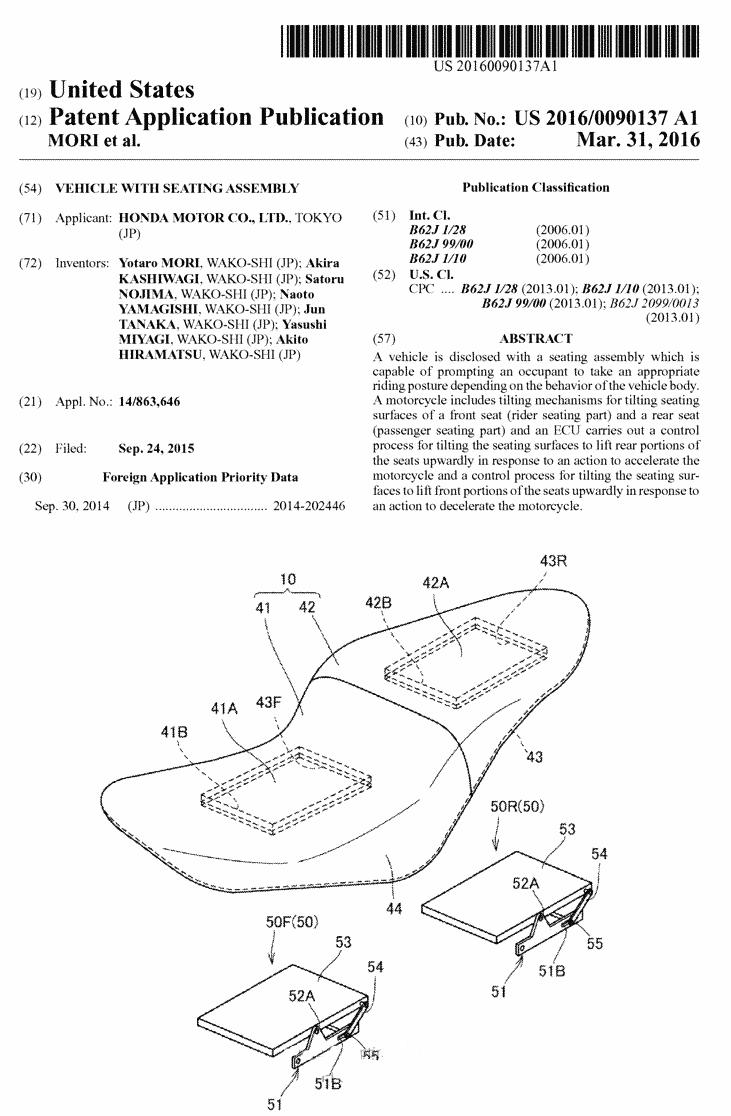
In FIG. 2, the outer profile of the occupant seat 10 is indicated by the two-dot-and-dash lines. The front seat 41 houses therein a tilting mechanism 50F for tilting the seating face 41A of the front seat 41, whereas the rear seat 42 houses therein a tilting mechanism 50R for tilting the seating face 42A of the rear seat 42.
The tilting mechanisms 50F and 50R are supported on the rear frame 25 that functions as a seat frame. An example of structure with which the tilting mechanisms 50F and 50R that are fixed to the rear frame 25 are housed in the occupant seat 10 will be described below.
FIG. 3 is a perspective of the occupant seat 10 removed from the vehicle body. The occupant seat 10 has upwardly recessed cavities 41B and 42B defined respectively in the front seat 41 and the rear seat 42. The cavities 41B and 42B are formed by providing recessed shapes that correspond to the cavities 41B and 42B in the cushion body 44 in the front seat 41 and the rear seat 42 and providing openings 43F and 43R, through which the cavities 41B and 42B are open downwardly, in the seat bottom plate 43.
The tilting mechanisms 50F and 50R are rigidly fixed to the rear frame 25 by fasteners (e.g., fastening bolts). The occupant seat 10 is installed, from above, on the tilting mechanisms 50F and 50R, thereby housing the tilting mechanisms 50F and 50R respectively in the cavities 41B and 42B in the front seat 41 and the rear seat 42.
The tilting mechanisms 50F and 50R are identical in structure to each other, and have identical parts denoted by identical reference characters. The tilting mechanisms 50F and 50R will hereinafter be referred to as a tilting mechanism 50 unless they are to be distinguished from each other. The tilting mechanism 50 will be described below.
As shown in FIGS. 2 and 3, the tilting mechanism 50 includes a pair of left and right bases 51 fixed to the rear frame 25, a pair of left and right swing supports 52 extending upwardly from the respective bases 51, and a seat 53 vertically swingably supported on the swing supports 52 by a swing shaft 52A extending in the transverse directions of the motorcycle 1.
The bases 51 include elongate members which extend in the longitudinal directions of the vehicle body. The bases 51 have grooves 51B defined therein which extend therethrough in the transverse directions of the vehicle body and also extend in the longitudinal directions of the vehicle body.
A single joint shaft 55 that interconnects ends of a pair of left and right link arms 54 is inserted in the grooves 51B in the left and right bases 51. The joint shaft 55 is movable in the grooves 51B in the longitudinal directions of the vehicle body, and the link arms 54 have their proximal ends coupled to the bases 51 for movement along the grooves 51B in the longitudinal directions of the vehicle body. The link arms 54 are in the form of bars whose distal ends angularly movably coupled to the seat 53.
The seat 53 includes a flat plate having a size fitted beneath each of the seating faces 41A and 42A of the front seat 41 and the rear seat 42. The seat 53 is disposed in each of the cavities 41B and 42B in the seats 41 and 42 and has an upper surface 53A held against the lower surface of the cushion body 44. The seat 53 is supported on each of the bases 51 for vertically swinging movement about the swing shaft 52A. The seat 53 has a portion spaced from the swing shaft 52A in a longitudinal direction of the vehicle body (a rearward direction in this approach) and coupled to the distal ends of the link arms 54. Therefore, when the proximal ends of the link arms 54 are moved along the grooves 51B in the bases 51, the seat 53 is angularly moved or turned about the swing shaft 52A, changing its angle of tilt.
The tilting mechanism 50 includes an actuator 60 (FIG. 2) for moving the proximal ends of the link arms 54 along the grooves 51B in the bases 51. The actuator 60 is a linear actuator having a movable member 60A that is linearly movable in the directions along which the grooves 51B extend (in the longitudinal directions of the vehicle body). The actuator 60 is fixed to the rear frame 25 or the bases 51, and the movable member 60A is connected to the joint shaft 55 that interconnects the proximal ends of the left and right link arms 54.
The actuator 60 includes a ball screw mechanism having a ball screw that is rotatable about its own axis by a motor to linearly move the movable member 60A. When the motor is energized to rotate its output shaft in one direction or the other, the movable member 60A is pushed (moved rearwardly) or pulled (moved forwardly). The angular displacement of the output shaft of the motor is controlled to adjust the position of the movable member 60A, thereby changing the position of the proximal ends of the link arms 54 in the longitudinal directions of the vehicle body.
When the position of the proximal ends of the link arms 54 in the longitudinal directions of the vehicle body is changed, the angle of tilt of the seat 53 is changed, causing the cushion body 44 to move the seating surfaces 41A and 42A in a manner to follow the movement of the seat 53, so that the seating surfaces 41A and 42A are tilted essentially in the same manner as the seat 53 is tilted. In this fashion, the seating surfaces 41A and 42A are angularly variable between a neutral position in which the seating surfaces 41A and 42A lie flatwise horizontally, a rear-up position in which the seating surfaces 41A and 42A have rear portions tilted upwardly, and a front-up position in which the seating surfaces 41A and 42A have front portions tilted upwardly.
FIG. 4 is a view showing how the postures of the front seat 41 and the rear seat 42 are changed by the respective actuators 60, FIG. 4A showing a state in which both the front seat 41 and the rear seat 42 take the neutral position, FIG. 4B a state in which the front seat 41 and the rear seat 42 take the rear-up position, and FIG. 4C a state in which the front seat 41 and the rear seat 42 take the front-up position. The state in which both the front seat 41 and the rear seat 42 take the neutral position is also referred to as a state in which “the occupant seat 10 takes the neutral position.” The state in which both the front seat 41 and the rear seat 42 take the rear-up position is also referred to as a state in which “the occupant seat 10 takes the rear-up position.” The state in which both the front seat 41 and the rear seat 42 take the front-up position is also referred to as a state in which “the occupant seat 10 takes the front-up position.”
As shown in FIG. 4A, when each of the actuators 60 moves the positions of the proximal ends of the link arms 54 to respective longitudinally intermediate positions in the grooves 50B, the upper surface 53A of the seat 53 lies flatwise horizontally, holding the seating surfaces 41A and 42A of the occupant seat 10 in the neutral position where they lie flatwise horizontally, whereupon the occupant seat 10 takes the neutral position.
As shown in FIG. 4B, when each of the actuators 60 moves the positions of the proximal ends of the link arms 54 to respective rear ends of the grooves 51B, the upper surface 53A of the seat 53 is tilted with its rear portion lifted upwardly, holding the seating surfaces 41A and 42A of the occupant seat 10 in the rear-up position where their rear portions are lifted upwardly, whereupon the occupant seat 10 takes the rear-up position.
As shown in FIG. 4C, when each of the actuators 60 moves the positions of the proximal ends of the link arms 54 to respective front ends of the grooves 51B, the upper surface 53A of the seat 53 is tilted with its front portion lifted upwardly, holding the seating surfaces 41A and 42A of the occupant seat 10 in the front-up position where their front portions are lifted upwardly, whereupon the occupant seat 10 takes the front-up position.
According to this approach, when the state in which the occupant seat 10 takes the rear-up position as shown in FIG. 4B is reached in response to an action to accelerate the motorcycle 1, the buttocks of the occupants (rider, passenger) seated on the seating surfaces 41A and 42A of the occupant seat 10 are rendered difficult to move rearwardly, and the centers of gravity of the occupants are shifted forwardly, prompting the occupants to take seating postures in preparation for acceleration.
When the state in which the occupant seat 10 takes the front-up position as shown in FIG. 4C is reached in response to an action to decelerate the motorcycle 1, the buttocks of the occupants seated on the seating surfaces 41A and 42A of the occupant seat 10 are rendered difficult to move forwardly, and the centers of gravity of the occupants are shifted rearwardly, prompting the occupants to take seating postures in preparation for deceleration.
When the state in which the occupant seat 10 takes the neutral position as shown in FIG. 4A is reached in case an action to accelerate the motorcycle 1 or an action to decelerate the motorcycle 1 is not taken, the occupants are prompted to take seating postures not in preparation for acceleration or deceleration or more relaxed seating postures for easily changing seating positions.
FIG. 5 is a block diagram showing an ECU (Electronic Control Unit) 100 for controlling the actuators 60 and peripheral devices. The ECU 100 is an electric unit including a computer and various electronic parts including at least a memory and a processor in which the memory is a non-transitory computer readable medium for storing data and computer instructions for controlling the processor. The ECU 100 functions as a controller for controlling various components on the vehicle body which include the actuators 60.
As shown in FIG. 5, sensors for detecting information of various areas of the motorcycle 1, switches, etc., as well as the actuators 60, are connected to the ECU 100. Specifically, those sensors and switches include a throttle opening sensor 101 for detecting the opening (throttle opening) of throttle valves actuated by the rider, a vehicle speed sensor 102 for detecting a vehicle speed, an Ne sensor 103 for detecting an engine rotational speed, an acceleration sensor 104 for detecting an acceleration, a gear position sensor 105 for detecting a present gear, a clutch detection switch 106 for detecting the turning-on (transmitted power cut off) or the turning-off (power transmitted) of the clutch mechanism, a gyro sensor 107 (angle-of-tilt sensor) for detecting a tilt (roll angle) of the vehicle body, a steering angle sensor 108 for detecting the steering angle of the front wheel 5 (or the handle 4), a navigation device 109, a seat position sensor 110 for detecting whether or not the seating surface 42A of the rear seat 42 is in a predetermined position (the neutral position in this approach), a brake switch 112 for detecting whether or not the rider is taking an action to brake the motorcycle 1, and a brake fluid pressure sensor 113 for detecting a brake fluid pressure.
The brake fluid pressure sensor 113 detects whether the brake is operating or not, i.e., whether or not the rider is braking the motorcycle 1, on the basis of the brake fluid pressure. The accuracy with which to detect whether or not the rider is braking the motorcycle 1 is made higher by using the signals from both the brake switch 112 and the brake fluid pressure sensor 113 than by using either one of those signals. FIG. 5 shows part of the devices that are connected to the ECU 100. The ECU 100 also performs such as engine control (intake control and ignition control).
FIG. 6 is a flowchart of a method of controlling the occupant seat 10. In step S1, the ECU 100 determines whether or not the vehicle speed is zero on the basis of the detected signal from the vehicle speed sensor 102. If the vehicle speed is zero, then the ECU 100 determines whether or not the motorcycle 1 is ready to start (step S2). In step S2, the ECU 100 determines whether or not predetermined conditions for judging that the motorcycle 1 is ready to start are satisfied. More specifically, the ECU 100 decides that the motorcycle 1 is ready to start if the clutch is turned on (transmitted power cut off), the transmission gear is other than a neutral position, and the rider is braking the motorcycle 1, on the basis of the detected signals from such as the clutch detection switch 106, the gear position sensor 105, and the brake switch 112.
If the ECU 100 decides that the motorcycle 1 is not ready to start, then the ECU 100 determines whether or not the front seat 41 and the rear seat 42 take the neutral position, i.e., whether or not the occupant seat 10 takes the neutral position, on the basis of the detected signal from the seat position sensor 110 (step S3). If the front seat 41 and the rear seat 42 do not take the neutral position, then the ECU 100 performs a returning control process for operating the actuators 60 to return the front seat 41 and the rear seat 42 to the neutral position (step S4). In the returning control process, the ECU 100 returns the front seat 41 and the rear seat 42 to the neutral position by smoothly changing the angular velocities of the front seat 41 and the rear seat 42 in order not to make the passenger feel strange and uncomfortable, e.g., performs a velocity control process for changing the angular velocities according to a sine-wave pattern. If the front seat 41 and the rear seat 42 take the neutral position, then the ECU 100 temporarily finishes the control process and thereafter carries out step S1.
If the ECU 100 decides that the motorcycle 1 is ready to start in step S2, then the ECU 100 carries out a first seat rear-up control process (step S5). The first seat rear-up control process is a control process for tilting the rear portions of the front seat 41 and the rear seat 42 upwardly to a predetermined rear-up position (corresponding to the position shown in FIG. 4B). More specifically, the ECU 100 tilts the rear portions of the front seat 41 and the rear seat 42 upwardly stepwise to a stroke position which is up to one half the full stroke thereof. The front seat 41 and the rear seat 52 are now in the state in which they take the occupant seat 10 takes the rear-up position, prompting the occupants seated respectively on the seating surfaces 41A and 42A of the occupant seat 10 to take riding postures in readiness for the starting of the motorcycle 1. Since the rear seat 42 is moved stepwise, the movement of the front seat 41 and the rear seat 42 is clearly indicated to the occupants, and the passenger is prompted to pay attention to the starting of the motorcycle 1.
If the vehicle speed is not zero, then the ECU 100 determines whether or not the acceleration of the vehicle body falls within a predetermined range (step S6). The predetermined range refers to a range of slow accelerations and decelerations including zero acceleration, i.e. a range of accelerations in which it is not necessary to tilt the front seat 41 and the rear seat 42. Stated otherwise, the predetermined range is set to a range of accelerations suitable for the front seat 41 and the rear seat 42 to take the neutral position (for the occupant seat 10 to take the neutral position).
In this case, the ECU 100 determines whether the motorcycle 1 is accelerating (the vehicle speed is increasing) or decelerating (the vehicle speed is decreasing) on the basis of the acceleration detected by the acceleration sensor 104. If the motorcycle 1 is accelerating, then the ECU 100 makes an acceleration correction to estimate an acceleration to be generated after an infinitesimal time from the accelerator opening and the engine rotational speed. If the motorcycle 1 is decelerating, then the ECU 100 makes a deceleration correction to estimate a negative acceleration (deceleration) to be generated after an infinitesimal time on the basis of at least either one of the brake switch 112, the brake fluid pressure, the accelerator opening, and the engine rotational speed. The ECU 100 then makes the decision in step S6 on the basis of the corrected acceleration or deceleration. The ECU 100 is thus able to determine the acceleration on the basis of the acceleration of the vehicle body after an infinitesimal time.
For estimating an acceleration to be generated after an infinitesimal time from the accelerator opening and the engine rotational speed, since the acceleration varies depending on how large the running resistance is, it is preferable to hold characteristic data of the running resistance in advance, specify a running resistance in advance on the basis of latest values of the accelerator opening, the engine rotational speed, and the vehicle speed change, and determine an acceleration from marginal drive power in view of the characteristic data of the specified running resistance. For example, data descriptive of the characteristics of the engine rotational speed, the accelerator opening, and the acceleration in a graph representing drive powers on its vertical axis and speeds on its horizontal axis may be stored as characteristic data of the running resistance, and an acceleration may be determined on the basis of the data thus stored.


